FarscanViz
ACPDR301T1 Life Detection Radar
ACPDR301T1 Life Detection Radar
Couldn't load pickup availability
Technical Exchange
01 PART: Technical Introduction
Life Radar Overview
• Launched 60GHz vital sign detection radar in Q2 2022
• Applied to Passenger Car CPD (Child Presence Detection) and Commercial Vehicle leftover living body detection
• Radial distance ≥2.7m (top-mounted)
• Enables in-vehicle personnel position detection
• Low missed detection rate by using breathing and limb micro-movement information for detection
• Low false alarm rate by filtering interference such as tapping and vibration
• Compact size for easy integration into the ceiling
• Short startup and response time
• Optional installation positions
• Sleep current: <1mA @12V & 24V
Specification Parameters
|
ACPDR301T1 Life Detection Radar |
|
|
Indicator |
Value |
|
Operating Frequency Band |
60GHz ~ 64GHz |
|
Peak EIRP |
≤18dBm |
|
Ranging Range |
0.053m~2.7m |
|
Range Resolution |
0.053m |
|
FoV (Field of View) |
120° (Azimuth, Elevation) |
|
Angle Measurement Accuracy |
±1° (Azimuth, Elevation) |
|
Speed Measurement Range |
±1.7m/s |
|
Speed Resolution |
0.0154m/s |
|
Data Refresh Rate |
<1s |
|
Operating Voltage |
8~32VDC, Type 24VDC |
|
Peak Power Consumption |
≤3.3W |
|
Peak Current |
≤280mA@12VDC<br/>≤140mA@12VDC |
|
Quiescent Current |
≤1mA@12VDC & 24VDC |
|
Operating Temperature |
-40℃~+85℃ |
|
Storage Temperature |
-40℃~+105℃ |
|
Relative Humidity |
0% - 95% (±5%) |
|
Air Pressure |
86kPa~106kPa |
|
Dust and Water Sealing |
IP5K2 |
|
Overall Dimensions (L×W×H) |
80mm45mm14mm |
|
Weight |
<100g |
|
Operating Life |
10 years |
|
Shock Resistance |
500m/s²@ 6ms half-sine<br/>(10 times in three directions) |
|
Vibration Resistance |
20[(m/s²)²/Hz]@10Hz /0.14[(m/s²)²/Hz]@1000Hz peak |
Radar Features
|
Company |
S Company |
b Company |
|
|
Performance Parameters |
STA79-5 |
MOD620 |
ACPDR301T1 |
|
Operating Frequency [GHz] |
77~81 |
60~64 |
60~64 |
|
Ranging Range [m] |
0.1~1 |
0.1~2.5 |
0.053~2.7 |
|
Ranging Accuracy [m] |
±0.04 |
/ |
±0.053 |
|
Range Resolution [m] |
0.04 |
0.375 |
0.32 |
|
Speed Measurement Range [m/s] |
/ |
/ |
-1.7~+1.7 |
|
Speed Measurement Accuracy [m/s] |
/ |
/ |
±0.04 |
|
Speed Resolution [m/s] |
/ |
/ |
0.0154 |
|
Azimuth FoV [°] |
±60 |
±60 |
±60 |
|
Elevation FoV [°] |
±10 |
±30 |
±60 |
|
Peak Power Consumption [W] |
1.8W |
±0.3°@0° |
3.3W |
|
Quiescent Current |
/ |
/ |
<1mA |
|
Dimensions [mm x mm x mm] |
92×47.4×18.3 |
55×45×14 |
67x56.7x16.4 |
Overall indicators are on par with international mainstream radars, and some indicators are superior.
Commercial Vehicle Coverage Solution
• Radar Coverage: 10m2.3m1.9m
• Installation Position: Central top mounting, longitudinal spacing ≤2.7m
• Installation Roll Angle: Parallel to the floor surface, error ±2°
• Installation Tilt Angle: Parallel to the floor surface, error ±2°
• Aesthetic Solution: Concealed installation & others
Concealed Installation Behind Honeycomb PP Board
Passenger Car Coverage Solution
• Meets Euro_NCAP 2023 CPD 4-point scoring requirements
• Functions: When there are living bodies in the vehicle, provides early warning through headlight flashing and horn honking; if the warning is ignored, contacts the owner via eCall
• Alarm Levels: Primary alarm, secondary alarm
• Equipped with system self-inspection function
• Supports UDS diagnosis and diagnostic flashing
• Supports CAN-OTA upgrade
• Supports bootloader
• Supports fault diagnosis
• Supports occlusion detection and alarm
• Supports offline calibration and after-sales calibration
• Supports network wake-up
Concealed Installation in the Ceiling
The above covers 3.0m2.3m0.7m for 7-seater commercial vehicles and can meet the coverage requirements of other small vehicle models.
Radar Structure and Installation
• Bracket Options: Sheet metal bracket or plastic bracket
• Fixing Method: M6 bolt + nut fixation
Structural Explosion Diagram: Cover Plate → Radar Board → Thermal Conductive Gel → Rear Shell/Antenna Cover → Self-tapping Screws
Customizable sheet metal brackets and plastic brackets; the second structural scheme is not mold-opened, and brackets are customized according to actual installation needs.
Interface
• Interface Model: mini50-10P
○ Male Connector: 349681801
○ Female Connector: 349671001
• Connector Information:
○ Insertion Force: <75N, Extraction Force: <100N
○ Pin Pitch: 1.8mm
• Equipped with IGN interface for hardware wake-up
• CAN Bus Interface:
○ Communication Rate: ~500kbps
○ With wake-up function
|
Pin Number |
Definition |
Meaning |
|
1 |
NC |
Reserved Pin |
|
2 |
NC |
Reserved Pin |
|
3 |
NC |
Reserved Pin |
|
4 |
NC |
Reserved Pin |
|
5 |
NC |
Reserved Pin |
|
6 |
GND |
Ground |
|
7 |
V-CANL |
Vehicle CAN- |
|
8 |
V-CANH |
Vehicle CAN+ |
|
9 |
KL30 |
Power Input |
|
10 |
KL15 |
Wake-up |
Installation Cover Requirements
• Shape: As flat as possible, uniform thickness, no sharp structures
• Hydrophobicity required
• Angle α between radar beam and cover ≤70°
• Distance D between radar and cover >5mm
• Cover Material: Plastic (excluding carbon fiber and metal)
• Recommended Materials and Thicknesses (integer multiples of the values in the table are acceptable):
|
Material |
Optimal Thickness t (mm) |
|
ABS |
3.51 |
|
PP |
4.04 |
|
PA |
3.74 |
|
PC |
3.71 |
• Painting Requirements: Paint should not contain metal ions; if a small amount of metal ions is necessary, performance evaluation by Chongqing Ruixing is required.
Appearance Dimensions
• Overall Dimensions: 804514 (mm)
• Body Dimensions: 664514 (mm)
• Installation Feature Dimensions: 3*Φ3.5 (mm), M3 bolt
• Weight: <100g
Smaller size than competitors from SS\BT companies
Structural Composition
|
Serial Number |
Part |
Material |
Dimensions |
Weight |
Origin |
Process |
Quantity |
|
1 |
Rear Shell/Antenna Cover |
PBT-GF30 or PC (black) |
804514 |
31g |
China |
Injection Molding |
1 |
|
2 |
Cover Plate |
ADC12 |
66457 |
40g |
China |
Die Casting |
1 |
|
3 |
PCBA |
FR4 + Al surface |
60301.6 |
15g |
China |
SMT |
1 |
|
4 |
Self-tapping Screw |
304 |
PA2*8 |
2g |
China |
Purchased Finished Product |
4 |
|
5 |
Thermal Conductive Gel |
- |
15*15 |
0.2g |
China |
Purchased Finished Product |
1 |
|
6 |
Label |
- |
- |
- |
- |
Laser Marking |
- |
Complies with ISO shock and vibration standards, see DV compliance for details
Thermal Simulation
• Optimized thermal design with chip junction temperature rise <25℃, meeting junction temperature requirements
|
Serial Number |
Chip |
Simulated Tj (℃) |
Temperature Rise (K) |
|
1 |
AWR6843AOP |
88.78 |
2.78 |
• Internal Heat Dissipation:
○ MCU heat is conducted to the shell through PCB and heat sink
○ Heat dissipation through shell vents and natural conduction
|
Part Name |
Material |
Thermal Conductivity (W/mK) |
|
Shell |
PBT-GF30 or PC |
0.28 |
|
Cover Plate |
ADC12 |
220 |
|
PCB |
FR4 |
8.3 (in-plane)<br/>0.5 (vertical) |
|
Thermal Conductive Silicone |
Silicone |
3 |
|
Chip |
Si |
150 |
|
Pressfit Pin |
Bronze, C51000 |
438 |
Antenna Design
• Antenna Type: On-chip patch 2D antenna array
• Gain: 5dB
• Advantages: Reduces the impact of feeder insertion loss on performance
Hardware Architecture
• Operating Frequency: 60G~64G
• Voltage Range: 8~32V
• Operating Current: <0.28A max@DC12V
• Wake-up Modes: IG, CAN fixed frame
• CAN Rate: 500kbps, 2Mbps adjustable
All hardware indicators meet technical requirements
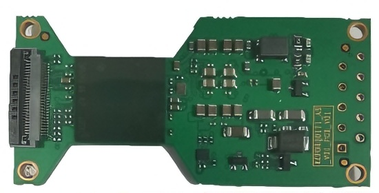
PCB Board
• Dimensions: 60mm*30.35mm
• Process: FR4 (simple process, low cost)
• Consistent circuit and interface across boards
• Optimized PCB shape to ensure radar antenna radiation performance
Detection and False Alarm Testing
• Detection Test Results:
○ Office Environment: Meets requirements
○ In-vehicle (Rearview Mirror, B-pillar, Rear Seat Top): Meets requirements
• False Alarm Test Results:
○ No false alarms from external interference: Meets requirements
|
Test Item |
Test Method |
Test Results |
|
|
|
|
|
Test Position |
Expected Test Result |
Result |
|
In-vehicle Living Body Detection |
Tested living body (human) sits in each seat with doors and windows closed |
All positions |
Prompt for presence of vital signs |
Qualified |
|
External Interference Test |
1. No living bodies in the vehicle, doors and windows closed.<br/>2. External living bodies approach the vehicle or cling to any part of the vehicle. |
Outside the vehicle near doors, personnel clinging to window glass |
No vital signs detected |
Qualified |
02 PART: Cooperation Cases
• Magna Design Win
• BYD-EM2E Model Matching
• Yutong Bus School Bus Project
Cooperation Case 1: Magna OHC Technology Demo
• Completed technical development: Meets in-vehicle life detection, anti-intrusion function, and no false alarms for external targets
• Cooperated with Magna for customer docking: Integration test in Magna OHC
• Newly added function: Intrusion detection function
• Full coverage of the entire vehicle area, effective detection of stationary targets, no false alarms from interference.
Cooperation Case 2: BYD-EM2E Model Matching
• Radar performance meets vehicle model requirements, follow-up business docking in progress
Cooperation Case 3: Yutong School Bus Living Body Leftover Detection System Project
• Goal: Enhance school bus safety by adding living body leftover detection system
• Technical Progress:
○ Completed: Development of single radar meeting performance requirements
○ In Progress: Development of living body detection system
• Highlight: Excellent anti-interference performance (resistance to kicking, jumping outside the monitoring area)
• Single radar performance is superior to mass-produced competitors' products.
Thank You for Watching!
|(注:文档部分内容可能由 AI 生成)
Share